Saturday, November 23, 2013

Shapeoko CNC router Electronics Upgrade - Part 2: Finishing the Enclosure and Electronics Mounting Parts

Preparing the Enclosure for the Electronics

I had to print three parts to get everything to fit snugly inside my new enclosure.  First, I needed a mount for my Raspberry Pi.  I found an appropriate one on Thingiverse:  http://www.thingiverse.com/thing:37889 .

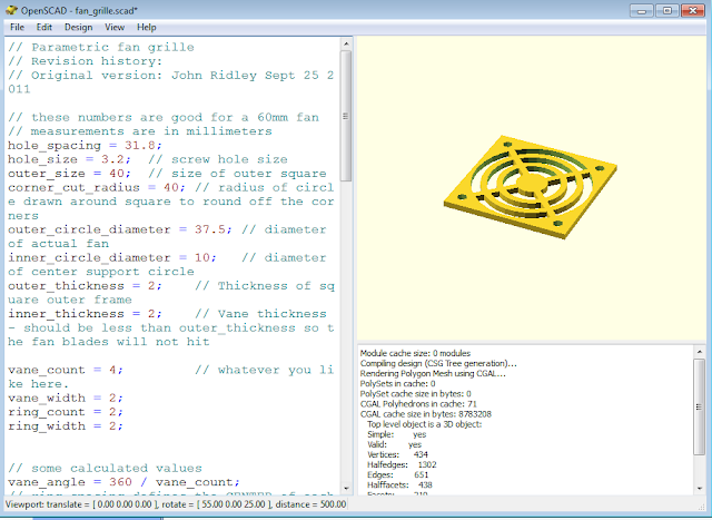
Next I needed an Arduino Uno/grbl mount:  http://www.thingiverse.com/thing:33327.  Finally, I needed a fan grille, but I could not find any out there that I could download and print directly.  I then came across this wonderful parametric fan grille that one could download, configure and print, brilliantly written by John Ridley a couple of years ago.

I downloaded the scad file, opened it using OpenSCAD"The Programmers Solid 3D CAD Modeller" (free).  All I had to do was take some measurements with my caliper, enter all the parameters the program required and, voila! a perfect fan grille, perfectly sized, ready to be printed:


In a pleasant surprise, printing went off without a hitch.  Here are the printed parts:


The next step was to mount the emergency-stop button, fan and fan grille to the top of the box:


I then used screws and trapped nuts to put the rest of the enclosure together.


With the enclosure and mounting parts complete, I am ready for the next step:  Turn the Raspberry Pi into a dedicated gcode sender that can be wirelessly remote-controlled from any computer or tablet in the house.


Tuesday, November 19, 2013

Shapeoko CNC router Electronics Upgrade - Part 1: New Enclosure

Right now, my Shapeoko variant router works fine.  There are only a couple of issues that need to be resolved.  The main issue is that I need to use a laptop (that I would rather use elsewhere) to act as a g-code sender.  My thought is that the perfect scenario would be to replace that laptop with a Raspberry Pi running a g-code sender and a XRDP allowing me to remote into it over Wifi from any PC or tablet in the house.  If that scenario could work, I would be able to create an enclosure housing the Arduino Uno/grbl shield together with the Raspberry Pi.  I could then also include a cooling fan and a sorely-needed emergency-stop switch (until now, I have been using the power strip switch as a poor man's e-stop).

The Enclosure

I decided to mill my rectangular enclosure out of 1/4" plywood.  I want all parts to have finger joints and T-slots so that I can use screws and nuts to lock the enclosure together.  After a bit of research on how to do this I found a great, free T-slot Boxmaker extension to the also-great and free Inkscape design software that allows you to specify the box's parameters before it creates the box design for you.  These were my parameters for the enclosure:


The result was this:


I then saved it as a DXF file and opened it in my preferred CNC software:  CamBam.  The following steps were to rotate the parts (on my CNC router, my Y is longer than my X axis), delete unnecessary screw holes and T-slots, add holes for the fan and E-stop switch and wire and ventilation slots to the end pieces.  The final design for the enclosure looked like this:


So with chest full of air and heart full of pride, I start my cut...  Only to fail.  For some reason, my computer and grbl controller disconnect well into the cut.  I needed to re-zero the tool, which of course means finding that zero.  When it failed, it had already cut the following in red:


So I reset the system to 0, 0 and manually moved the bit to this point that Cambam said was at 100mm x 83mm:


I then instructed X to go to -100 and Y to go to - 83 and, voila:  the old zero was found.  I now once again reset the controller so that the new 0, 0 was recognized, disabled the previously-completed T-slot cuts, regenerated the gcode and got it to continue where it left off. 

Now, I will try to avoid boring you with the intervening failure that took so much of my time.  Sufficed to say that my machine was failing when trying to drill small holes.  It turned out that it was choking on the fact that these holes were made from thousands of useless lines of code.  Once I simplified those holes by replacing them with circles and regenerated gcode, all worked well.  

Once everything was set, I finally had my machine cut the enclosure parts from 1/4" Birch plywood.
 
This was the result:


I noticed one problem:  The E-stop switch will not fit a 1/4" thick surface, so I will need to consider a fix to this.  Otherwise, I am pleased with my first computer-generated finger-joint box.
 
On my next post, I intend to detail how to configure a Raspberry Pi to be a remote-controller for an Arduino/grbl-based CNC router such as Shapeoko.


Wednesday, November 6, 2013

Building a hexacopter drone with the help of CNC routing and 3D printing

After building a couple of 3D printers and a CNC router, I found that many of my friends would quite reasonably inquire as to what I actually make using these machines.  For a long time my reply was that I used them mostly to make 3D printer and CNC router parts, after a while allowing me to come to the realization that my obsession with these machines was, quite literally, feeding itself.

All that changes with my latest project:  to build a heavy-lifting, full-featured aerial hexacopter drone with as many parts as possible being CNC routed or 3D printed in-house.

The first thing that I had to settle on was what design to use.  I had been following the progress of many projects at DIY Drones.  One of their very active participants, Jeremy Guillory, published this blog post describing cutting a bunch of hexacopter frame parts out of Lexan (polycarbonate) using a water jet.  He also supplied the CAD DXF file that I could use to make those same parts with my CNC router.

The next step was to figure out what material to use.  People have been building multi-rotors out of almost every light/strong material imaginable.  At the Holy Grail high end is of course, carbon fiber.  But the cost is very high and if I mess up a cut, I waste a lot of money.  I could have also done it in fiberglass or Aluminum.  In the end, I was persuaded by a fellow I met at this year's NYC Makerfaire that I should use a material called Dibond.  Dibond is a composite material consisting of a polymer sandwiched between two super-thin sheets of Aluminum.  It is light, yet strong and rigid.  It also has some helpful vibration dampening qualities.  Best of all, it happens to be inexpensive.  I bought 5 1/8" Dibond sheets for about $10 each, shipping included.  Cutting all the parts required 1 and a half.  I had to kill the job at one point when an inadequately-secured part got sucked-in by the bit but I was able to zero out the CNC machine and continue.


The Aluminum arms can be acquired quite inexpensively from HobbyKing.com ($0.88 each!).

My goal, beyond documenting this build is to leave my fellow makers with instructions to build their own full-featured aerial robot at the lowest possible cost.

Stay tuned for more shortly.